
This was a very well designed model but unfortunately the parts were printed in A3 format.
Because the majority of modellers only have an A4 printer, including
myself, I’ve re-arranged the parts (without a reduction in scale) to fit onto A4
sized sheets.
4 of the parts were too big to fit onto A4 sheets so I divided each of
the 4 parts into 2 pieces each, using panel lines for the joining interfaces.
Another thing that I was not happy with was the tab positions. As a
personal preference, I don’t like tabs to alternate between two parts as I feel
that this gives rise to “wavy” join lines. I prefer the tabs to all be on the
one part so that a clean straight join is obtained.
The assembly guide of the original model only consisted of pictures with
no discernible sequence or part numbering so I have numbered all the parts on
the A4 sheets, using a modular numbering system.
The model was well designed to be built in modules, so I’ve kept to
this, starting with the main body (B).
As a personal preference, I find it easier to scribe all parts that bend
before cutting them out.
Once I am satisfied with each module, I will upload the relevant pdf
pages to Mediafire for you to download should you wish to build it.
Main body (Module 1).
BEFORE GLUING PARTS TOGETHER, CHECK THAT THE TABS DO NOT INTERFERE WITH
EACH OTHER – TRIM IF NECESSARY.
Join the base parts B to Ba and then re-enforce base B with 1mm card
using the template guide provided.

Assemble parts B3a & B4a and when dry, fit them to sides B3 &
B4. Note that there is an alignment dot on one of the tabs on each part. This
tab faces the front of the body.


Join parts B1 to B2 and then to Base B and sides B3 & B4.

Rear landing unit.
After assembling parts L1a, L1b, L1c & L1d, glue them to part L.

Now attach sides L2 & L3 to L.

Note that the front and rear bend slightly.

Add reinforcing card.

I recommend reinforcing the inside back and sides of the rear landing
gear recesses (L1a & L1b) with 1mm card.
Now attach this unit to the body.

This completes module 1. The files can be found here:-
http://www.mediafire.com/folder/e2cv2r9jdye20/Razor_Crest
Upper body (Module 2).
BEFORE GLUING PARTS TOGETHER, CHECK THAT THE TABS DO NOT INTERFERE WITH
EACH OTHER – TRIM IF NECESSARY.
Attached T to T1 and then glue on the card stiffeners.

Join parts TB2 to TB3 and TB4 to TB5.

Add card stiffeners to these assemblies.
Construct part TB7a and attach to part TB7.

Construct part TB7b as shown.

Now, attach TB7b to part TB7 by initially gluing the tabs as shown in RED.

Wait until completely dry and then glue the rest of the tabs around the
underneath of TB7b.

Attach TB7e to TB3 and then attach TB7.

Repeat for TB7f, TB5 & TB7.

Now attach this assembly to T1.

When dry, continue to attach this assembly to the base T, one tab at a
time.

Attach pieces TB7c & TB7d to TB6 (Note the raised edges).

Attach card stiffeners to TB6 and then glue TB6 to TB7.

Glue TB6a to TB6 and when dry attach to TB2 & TB4.


This completes module 2.
When dry, the two modules were joined together.

The files can be found here:-
http://www.mediafire.com/folder/e2cv2r9jdye20/Razor_Crest
Next step is the cockpit and front landing unit....Module 3.........
BEFORE GLUING PARTS TOGETHER, CHECK THAT THE TABS DO NOT INTERFERE WITH
EACH OTHER – TRIM IF NECESSARY.
There are modifications to the tabs on R & R1 (Page 03.pdf) and L4
is no longer required (Page 08.pdf). The modified pages have been uploaded.
I assembled the parts of the cockpit as per the original shapes but was
not happy with the way the canopy was joined and the method of the curve.

I decided to combine the 4 separate parts into one piece and make
alternative parts for the front curved side windows.

Assemble part L3.

Now curve the parts as shown.


Now glue the next tab, moulding the canopy with your fingers.

When completely dry, glue the next tab.

And finally, glue the rest of the tabs.


Assemble parts L, L1 & L2. Reinforce the back of L2 with 1mm card.

Start attaching part L to the cockpit by aligning the centre.

Gradually glue the tabs working from the centre.

I found that it was not very rigid where the cockpit attaches to the top
of the body so I cut out a section and glued in a 1mm piece of card underneath
the cut-out to flatten out the mounting position.

Start by attaching the cockpit to the body at the tab shown.

When dry, glue the corresponding tab on the right side of the cockpit.
Gluing the rest of the cockpit is a bit tricky and I found that the best way
was to use thick superglue for a quick bond.
Fit L4a & L4b and the front lamps. Any imperfections on the side
joins of the cockpit will be covered by front shields L4a & L4b.

Join R to R1.

Now glue the roof to the top of the body to the rear of the cockpit.

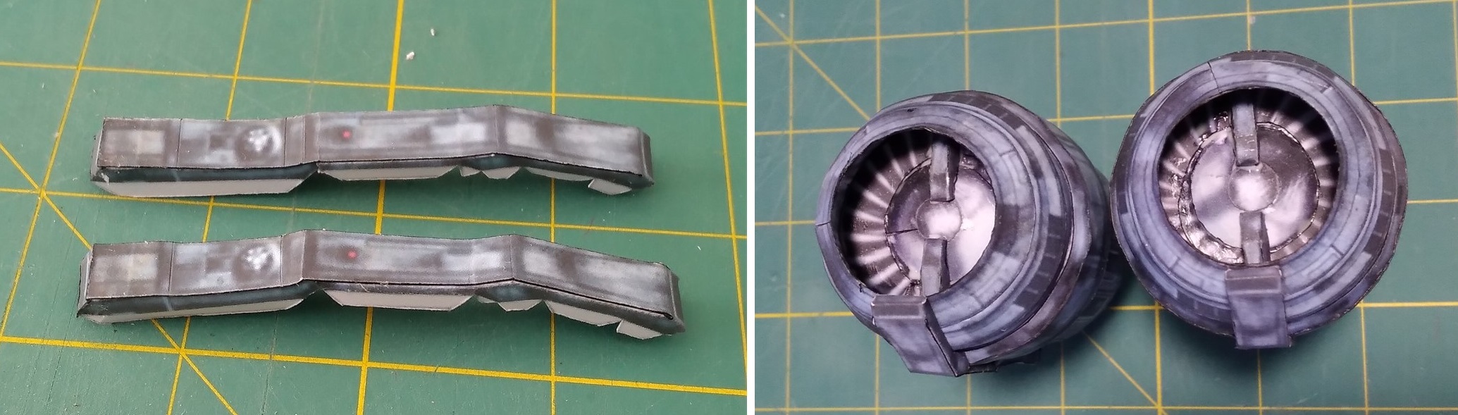
MODULE 4...ENGINES...
I decided to make 1mm card formers as there was no rigidity in the
engine units. This would also make it easier to keep their shapes when gluing
the various stages. Also, there was no inner cladding to cover the insides of
the engine intakes and exhausts so I added these also.
The only difference that I found between the two engines was that one of
them had a small piece out of the front of the cowl. For simplicity, I decided
to make both engines the same. Therefore they can be constructed together as
the parts are identical for each engine.
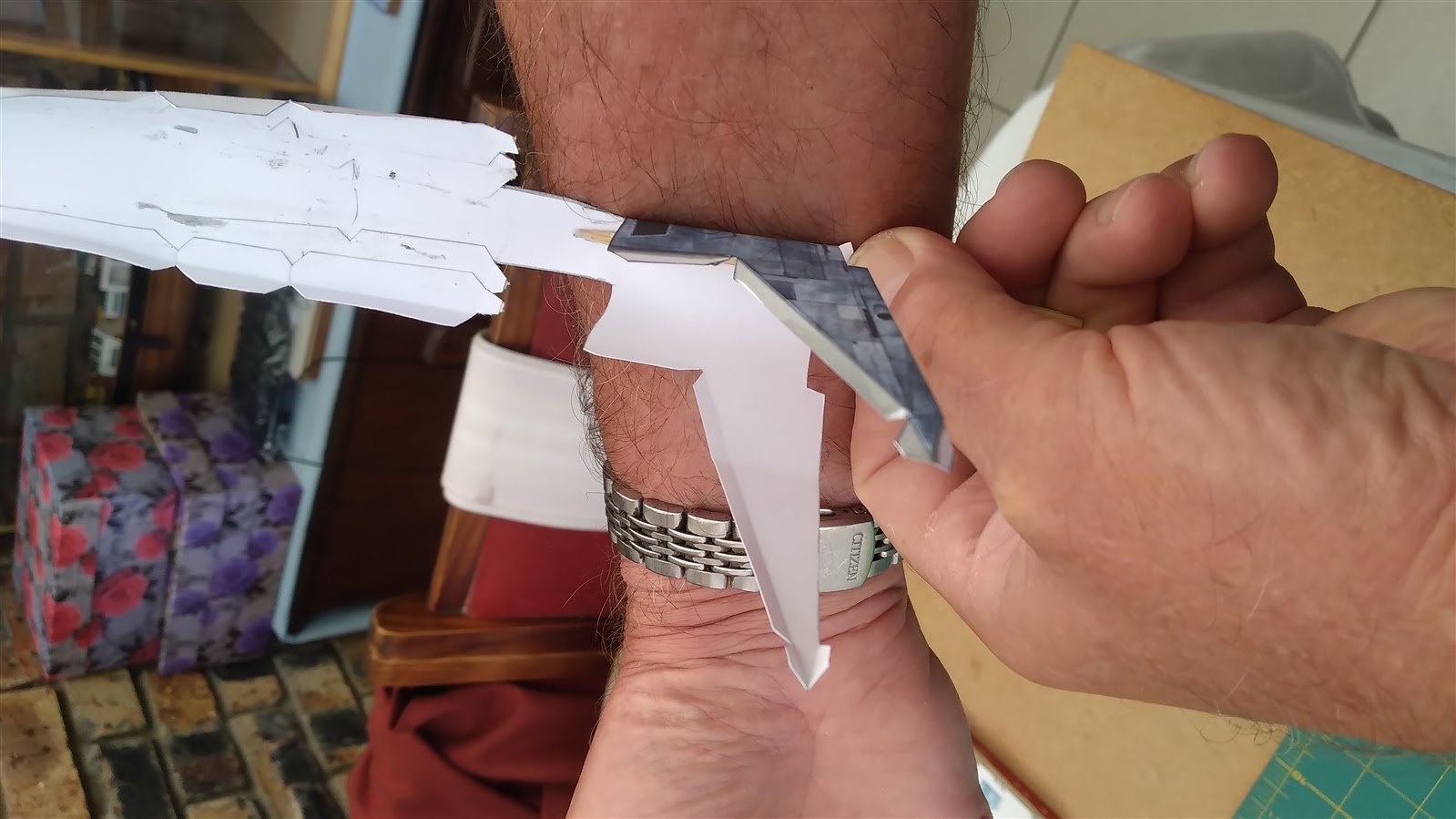
I was not happy with the original single piece front assembly part (E2) as
I felt that with the three bands joined, this complicated the gluing of the bands
to each other causing a “bump” where there were no tabs. I also found that
sometimes the parts did not line up properly.
I therefore decided to split this part into 3 separate bands which made
assembly easier and the parts fitted perfectly every time.
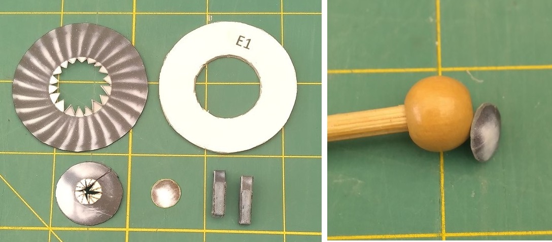
Parts E1.
I “domed” part E1a with a tool made from a skewer and wooden ball from a
craft shop.
For applying pva with a toothpick or paintbrush, I use an old margarine
lid on which I put a dab of pva. Any residue left over will peel off after
drying.

Assemble E1b with joiner J1 and assemble parts E1d.
Glue E1a to E1b (matching the colour pattern) and then attach E1b to
E1c.
When dry, glue this sub-assembly to former E1 and then attach 2 x parts
E1d.

Parts E2.
Assemble E2a with joiner J2, E2b with joiner J3 and E2c with joiner J4.
Glue assembly E1 inside E2a
midway between the front and the rear (the rear has square tabs).

Bend the triangular tabs of E2a inwards at 45°. Coat the inner edge of
E2b with pva and slide it over the tabs of E2a and gently work it so that it
fits neatly all around E2a without any tabs showing. Now gently crimp the tabs
with flat nosed tweezers.

Now glue the inner liner strip E2d in place as shown.

Now repeat this process with E2c.

Coil up the inner liner E2e and insert it into the cowl. Glue the top
corner in place as shown. When dry, run a bead of glue along the inside of the top
edge of E2c and fit the rest of the liner in place.

Join rings E3a with joiner J5, E3b with joiner J6 and E4a with joiner J7.
Attach E3a to ring E3b.

Flatten out the square tabs on E2a and then carefully run a bead of pva
along these tabs as shown.

Now slide ring E3b over the cowl assembly and fit onto the square tabs
in the same manner as the cowl rings were assembled.
Make sure that the parts E1d on the front of the intake fan are in line
with the red dot on ring E3b which will be the bottom of the engine.
Crimp as before then run a band of pva along the inside of the square
tabs to seal them.

Test fit former E3c, sanding a chamfer around the edge so that it is a
sliding fit in ring E3b.

Draw a line about 5mm inside E3b, run a bead of glue along it and push
former E3c into place.

Glue two tabs of ring E4a in place on E3b.

When dry, glue the rest of ring E4a in place.

Assemble ring E4b with joiner J8. NOTE that these parts are “handed”,
PORT & STARBOARD. This is the only difference in the two engines.
Run a bead of glue along the inside of the front edge of E4b and fit it
over the tabs of E4a, note that the red dot on E4b lines up with the red dot on
E3b.

Chamfer the edge of former E4c so that it fits into E4b. As with E3b,
draw a line about 5mm inside E4b, run a bead of glue along it and push former
E4c into place.

Assemble conical ring E4d with joiner J9. Join ring E4d to ring E4b.

Carefully chamfer the edges of former E4e so that it is a perfect flush fit
in the end of conical ring E4d. (Slide it in vertically and pull it back up
using bent tweezers). Make sure that its face is smooth.

Remove it and coat the inside edge of conical ring E4d with pva and then
refit E4e, pulling it back up so that it is flush with the top all around.

When dry, colour the outer edge of the former black. (I used a permanent
marker with a thin tip).

Trim disc E4f to fit and glue it on.

Assemble cone E5c with joiner J9 and then glue in the inner liner E5d
(it may need trimming).

Chamfer former E5a to fit flush at the back of E5c. Make sure both sides
are smooth. Glue disc E5b to the front of the former and when dry, trim it to
the former from the rear and colour the edge black.

Now glue it in place at the rear of cone E5c and when dry, glue it in
the centre of disc E4f.


Construct part E6 and then glue it to the engine.

https://www.mediafire.com/folder/e2cv2r9jdye20/Razor_Crest
I have decided to not mount the engines yet as I think that the upper
body needs another profiled cross member made from 1mm card placed across the
body from engine to engine to maintain the body shape and also profiled card at
each “wing” end where the engines mount.
I cut a 10mm x 180mm strip of 2mm card and chamfered the ends as shown.

This was glued in place across the body, in line with the panel marks as
shown. Note that it does not interfere with the triangular tabs.

The port engine was now glued in place. I found that the best position
for it to fit on the tabs was more or less midline although the engines on the
real ship were higher in relation to the wing. A liberal amount of pva was
spread on the wing tabs and the engine pushed into place.

The model was set in a vertical position to dry before fitting the
starboard engine in a similar fashion.

Any slight gaps in the fit were filled with pva using a paintbrush. This
would dry clear.
To finally cover any gaps in the joints between the engines and the
wings, wing fillets have been provided. Print them on 80 gm paper, test fit them
and then put a bead of pva along the joins and tease the fillets into place
with narrow tweezers. Run your finger along the join to collect any surplus
glue.
Once dry, this would not be noticeable (it dries shiny), as eventually
the model will be sprayed with clear acrylic lacquer to preserve the ink from
fading.


Armour.
These parts are left and right handed so be careful not to mix them up,
especially parts AL6 and AR6. If you bend them the wrong way when assembling 6a
& 6b, you might think the left one is the right one and vice-versa.
They are also very small so be careful. I’ve put spare ones on the
sheet.
I’ve separated part 6 into two parts as I found it easier to assemble.
The original part lacked space for tabs because of the closeness of the sides.
I separated part 2 into 3 parts, also to simplify the assembly.
I’ve dispensed with the original part 5 as will be explained when the
barrels (part 4) are fitted.
Assemble part 1 as shown.

Assemble part 2. 2a & 2b do not have tabs but are glued directly
onto part 2a.

Slide part 1 onto part 2 but not all the way. Put a ring of glue around
part 2 as shown then slide part 1 fully into place. Clean up any excess glue.

Now fit part 3.

The barrels (part 4) were then assembled and fitted with a piece of 3mm
dowel (I used a bamboo skewer), recessed about 2mm in from the front. The end
of a toothpick was then glued into the front of the barrel.

Small rings were made from 0.8mm brass wire as shown. These were then placed
onto the toothpicks and a ring of thick superglue put around the top of the
rings to form a cone shape.

The stem of the toothpick was painted metallic silver and the cone shape
metallic gold.

When dry the barrels were glued in place.

The weapons were now glued in place.


Parts 6a & 6b were now constructed and then glued in place.


This is the reason for the modification.......

A full set of pictures of the ship can be seen here......
Boy, would I love to have that model!
FRONT LANDING UNIT
Assemble parts FS1, FS2 & FS3. I decide to put a 5mm hole in parts 1
& 3 and fit a 4mm dowel (skewer) in FS2, 15mm long.

FS2 was then glued into parts 1 & 3.

FS4 was carefully assembled.

and when dry, assembly 1-3 was
glued in place.

This was then fitted underneath the front of the body and part FS5 was
then made and fitted.

REAR LANDING UNITS
The Rear landing units have been labelled LS(left sole) and RS(right
sole), numbers 1 to 7.
I would advise building the LEFT sole first so that you become familiar
with the assembly and correcting any mistakes before you repeat the process for
the RIGHT sole. Some of the parts are very fiddly and fragile so wait until
each gluing operation dries fully before continuing.
The assembly of LS parts 1-7 will also be relevant to RS parts1-7.
Start by cutting out LS1 and glue
the side pieces to the main body.

Because the side walls on LS2 are so fragile, I reinforced the bends on
the rear with thin strips of 80gm paper.

Now join part 1 to part 2.

Now start by gluing the side wall as shown. This is a bit tricky so dry
fit it first.

Carry on until all the side walls are glued in place. Now glue in a
piece of 2mm card to firm up the base.

When dry, finish closing in the sole.

Parts 3 & 4 are straight forward. If you want to use a 4mm dowel
(skewer) in part 8, cut out the holes in parts 3 & 4. (I will use a 4mm
skewer).

Again with part 5, reinforcing strips were fitted on the rear of the small
side walls.

Glue the side walls and then attach a 1mm piece of card to the base.
Glue the top by gluing at the points shown. When dry, glue along the rest of
the tabs, forming the bend at the other end.

Part 6 was also reinforced on the side walls and then assembled, with a
1mm piece of card to stiffen it.

Part 7 was reinforced with 1mm card.
If you did not make the rear sole parts together, now is the time to
make the starboard (RIGHT) ones.
I used a 4mm skewer so the tabs were cut off part 8.


Glue part 4 to the sole.

Dry fit part 8 to part 4 and trim if necessary but do not glue.
Dry fit part 8 to part 3, trim if necessary then glue into part 3.

If you have not built the model yet, I would recommend reinforcing the
inside back and sides of the front and rear landing gear recesses with 1mm
card.
Attach parts 3 to the hull, locating them centrally in the recesses.

Get something that’s 10mm thick to use as a spacer.
When parts 3 are fully set in the hull, stand the hull on a flat
surface, elevated if possible to make it easier to work on and place the 10mm
spacer under the rear, behind the rear landing legs and not in the way of the
soles which will be fitted now.

The rear landing legs can now be glued to parts 4. Leave to dry fully
before attaching parts 5 & 6 to the legs.

Finally, fit parts 7.

And that is the model finished. Most of the parts were prototype parts
so I will now build another one using the final pdf’s.


No comments:
Post a Comment