After building unique models in bottles, I needed a long term project,
so I revisited the pinball machine.
This is the initial general layout but will probably change as I progress and find alternative options.
I decided to get all the various light circuits and mechanical modules to work, before building the playfield itself.
I finally got the scoring circuit to work.
For the sound circuit, I found a circuit on YouTube that suited me.
Next was to design the rollover switch that would provide a pulse when
the ball rolled over it.
I got a pack of 20 micro switches from Takealot and modified them by
gluing a length of stainless steel wire to them with 5 minute epoxy and shaping
them as shown. The brackets were made from pvc electrical wall boxes.
Now to connect the switches to “playfield switch termination boards”.
These boards would connect the inputs from the switches to the “score
control board", and LEDs if required.
After a few weeks of breadboarding various chaser circuits,
I finally settled on this one.
This is the prototype proof of concept.
The
mountings were made from 4mm countersunk machine crews, superglued to the
plastic and then a fillet of baking soda and superglue made a permanent anchor
for them.
The next circuit
to create was a one-shot sequence LED chaser circuit for each of the top 5 ball
lanes. When the ball enters one of the 5 start lanes, it will go over the corresponding rollover switch and energise the set of LEDs in a one-shot
sequence.
Here is the
final working circuit.
That’s the
main electronics sorted, now to start on some of the mechanical elements.
The ball
plunger.
This was
made from a length of 12mm hardwood dowel, a door knob, some washers, 13mm ID aluminium
tube and a spring from a plunge router. The end of the rod was capped with a
rubber stopper and using a Dremel cutting disc, a groove was cut into the rod
behind the stopper to take a circlip which would retain the spring and washer.
Next are the
flipper mechanisms.
I built a
prototype jig to test the linkages and operation. This is where you correct all
your mistakes and create the template for the final version on the playfield.
The flippers
were made from wood and grooves routed front and back to hold the rubbers made
from “O” ring rubber cut to length and glued with cyanoacrylate (superglue).
The mounting
shafts were made from cup bolts, modified as shown.
The rubber
mounting pillars were made from plastic nail-in anchors.
These
comprised of a shaft and 2 anchor heads, cut to size.
I am trying
to do as much as I can mechanically and keep electrical operation to the
minimum in order to simplify repairs if necessary.
I now started to build the playfield.
Now to make
the springsets which fit behind the bumper and slingshot rubbers and increment
the score when operated. They will also operate a circuit which will give an
audible tone.
I had a coil
of 1,2mm stainless steel wire and the “spring sets” were made from this. The
spring set mounting blocks were made from a load of plastic shelf support
blocks that I had spare.
I’ve redesigned the ball return and new ball mechanisms and replaced the actuation knobs with slide levers.
The
prototype playfield is finally finished and mechanically tested.
The frame of
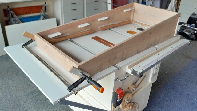
the cabinet is made.


No comments:
Post a Comment